Wednesday, 15 February 2012

Paradise...or is that Stereo?...Regained

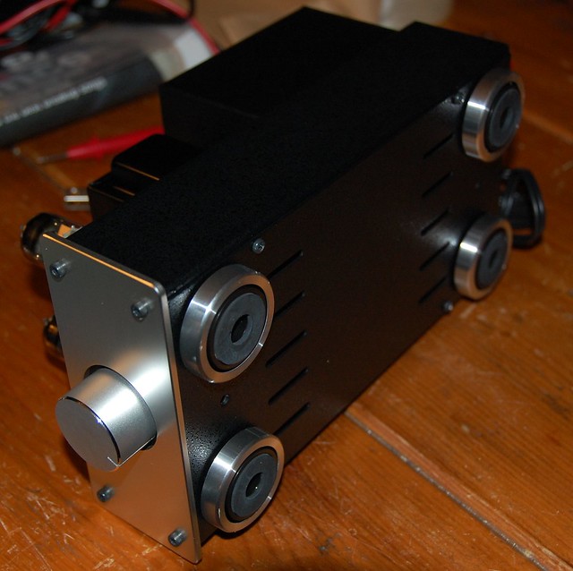
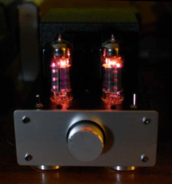
I managed to find the fault in the wiring that had my Elekit tube amp not performing as it should (see previous post). It took a bunch of steps to find it, though might have been easier if I had just started at the "other end". Or as my dad used to say, "it was in exactly the last place I looked", as if you would continue looking after you found whatever it was.

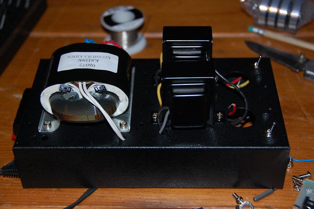
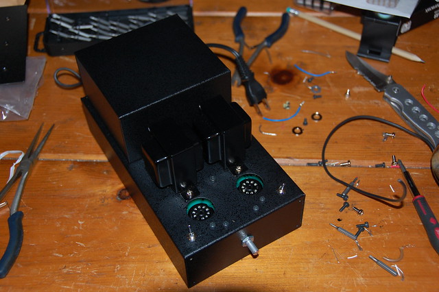
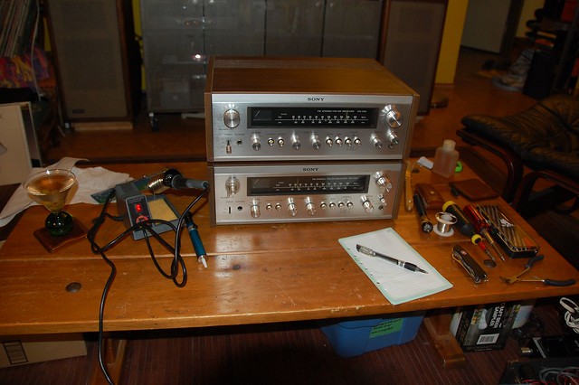
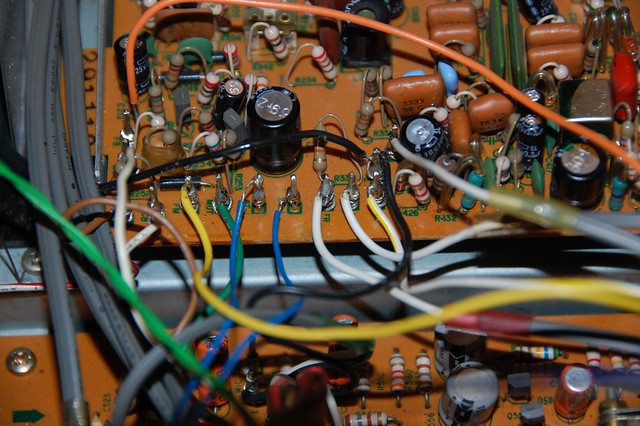
In looking for the problem, all the obvious steps were at first to check the external wiring. The input cables, output wires for the speakers, and even the speakers themselves were all swapped to no avail. I switched the tubes from one side to the other. Nope.

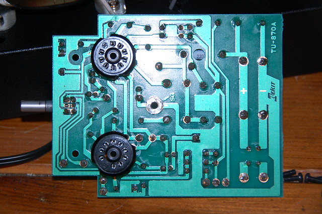
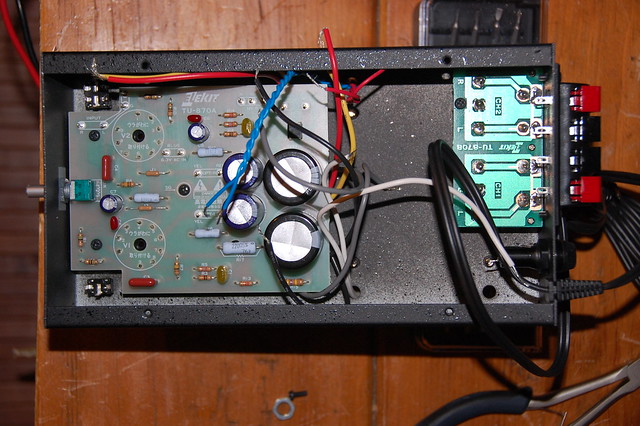
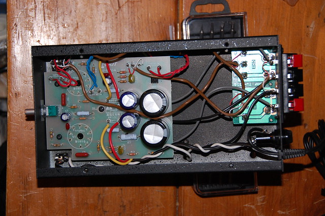
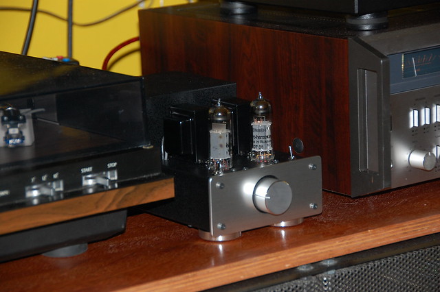
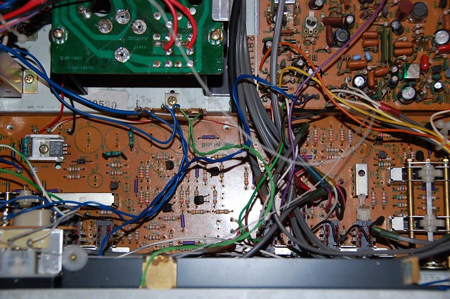
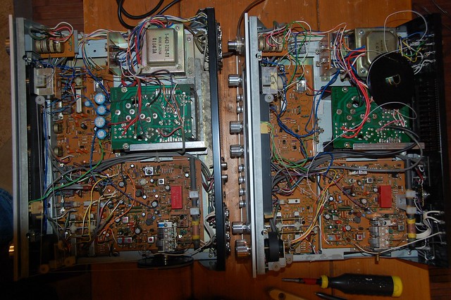
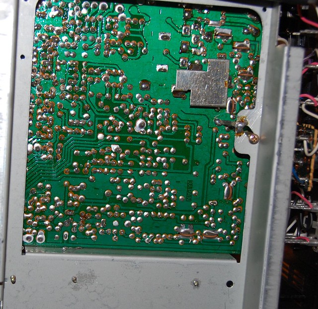
I then went inside. I poked and prodded at the various wires and examined solder joints and pretty much everything else. I then decided to actually reflow the solder junctions. This essentially means to melt the solder again, and maybe even add a bit, just in case there were any bad or cold joints. Nada.

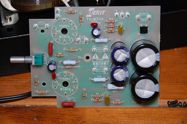
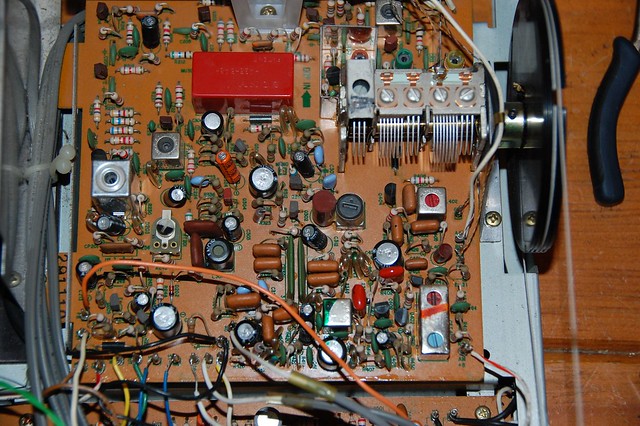
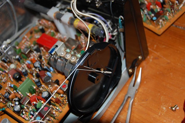
I suspected also that perhaps the fine shielded wire used to connect the PCB to the speaker terminals might be at fault as I may have shorted something there while stripping the very thin gauge wires. Close but not quite...

I removed some of those wires and added in one to bypass the potential short, and still no dice. Looking more closely I finally figured out that one of those skinny wires was heading to the wrong side of the speaker output. WHITE goes to RED not BLACK dammit!

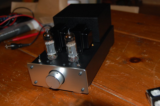
Once that was redone it plays just great! More listening reports will follow but whew!!


DSC_0405 crop

Saturday, 11 February 2012

Building a tube amplifier

Over at Audiokarma I was recently the recipient of some karma when one of the good folks there  offered an unbuilt tube amplifier kit for free, "just pay shipping". I was the first to jump in and say "I'll take it!" and picked it up a couple of weeks ago down at Point Roberts. The border guys were skeptical of my free amplifier kit asking what the value was. I said about $100 and after the guy opened the parcel my claim was reinforced by the fact that this kit had been sent from the importer to the guy in Illinois from Canada and the original label was on it, stating a declared value of $100. Ironically the amplifier had been sent from just down the road in Coquitlam in the first place, much closer to me than even Point Roberts. However if I had tried to buy it here at home I would have paid roughly 10 tens as much as the vendor lists it at $335!

http://www.vkmusic.ca/TU-870R.htm

The kit is an Elekit from Japan, model TU-870R. It came with 2 6BM8 tubes and a Hammond style black hammertone case. The entire kit was well packaged and parts packed in numerous small bags and other wrapping, and included step by step instructions in English and Japanese. Fortunately the instructions were also well translated with only a few small typos and fractured phrasing.


It's been a LONG time since I built a kit or any electronics from scratch. But late yesterday afternoon I dug in.

I laid out all the parts and went through a checklist to see if it was all there, and thankfully it was complete with perhaps a couple of extra screws and soldering pins. I didn't check the value of the different resistors and capacitors at this point but did do a count of each type. An optional capacitor was included in the kit designed to help the Signal to Noise ratio.

Wile the soldering station was getting hot, I moved to some other prep work. The printed circuit board was in one piece but had to be scored and broken into the main component board and the input connector board. I sanded the burrs from the scored edge just for tidiness.

DSC_0382


My soldering technique may be a bit rusty at times, but I pretty soon got it done. Reading some of the resistor values was probably the hardest part as these were tiny 1/4 watt types mostly (and my eyes are also a bit rusty!)  and the colour bands were a bit hard to make out. I got out my meter to check some of them to be sure. As I went along I also was checking off each of the steps I performed as the kit manual suggested.

DSC_0385

The tube sockets are installed on the face or foil side of the board and the rest of the doodads from the other side. The non-foil side had pretty clear markings for the placement of the different components and pins.


DSC_0386

The outside of the case soon had the power transformer and output transformers installed with the supplied hardware. The main case has been pre-drilled and tapped by the manufacturer. There are 2 switches, one for power and the other to select the source as there are 2 sets of RCA connectors for line level inputs (like CD or MP3 player).

DSC_0387

The 2 PCBs are mounted with stand-off posts and with the volume control nut for the main board and some small screws for the speaker and RCA terminals. I realized after I had soldered the connecting pins to the input board that I had done them from the wrong side of the board so I had to unsolder them and do it again. This board goes in foil side exposed so they are supposed to be the opposite of the main board but I initially missed that in the instructions.

DSC_0390

Above is before the internal wiring is complete and below is after. I discovered at this point I had made one other slight boo-boo here in that I had not yet installed the cover over the power transformer. I had to unscrew the PCBs to get at the mounting holes under them. It was getting late by now...

DSC_0391

The brown wires were also a bit tricky. They are 2 conductor shielded cable and had to be cut to specific lengths and carefully stripped and twisted, and they are very fine gauge. The black and white wires are the AC power and are twisted together to help prevent hum. The same goes for the 2 blue and red wires from the power transformer.

It's getting close now and I am about to close it all up and install the extra cabinet bits.

DSC_0392

The face plate is brushed aluminum and has some nice looking allen head screws for attaching it. The volume knob is also alumium and is held on with an allen head set screw and sits recessed into the silver face. The pins on the tubes were all straight and installed nice and firmly.

DSC_0394

The feet and bottom are on and look good. The bottom panel is drilled so that you can install 3 feet or four and since I have a nice level surface and don't believe there is any reason not to, I use all 4.

DSC_0395

And here is what it looks like, sandwiched in between my turntable and receiver. At this point I have it plugged in the back of the receiver's switched AC jack so the Mitsubishi has to be turned on. I'll rearrange that later, but at 2pm it was bed time!

DSC_0401

Build time was probably about 6 hours. I had to stop to make and eat supper (deepfried kalamari with greek salad, homous and pita...yummy!). I probably could have been a bit quicker but I was quite methodical and as mentioned, a bit out of practice.

DSC_0398

I hooked it up to my BIC Castle Clyde speakers and had a brief listen last night while I cleaned things up a bit. It sounds great and drives those speakers adequately, but I do have a problem. The left channel is quite a bit louder than the right. It is not a problem with the tubes, cables or the input as I switched everything around and even the speakers. I'll have to break it open again to check and the manual does give me a starting point suggestion in the troubleshooting area. There is a "resistance jumper" at the output terminals which I will check first. I hope it is that simple!

The source is my Rega Planet CD player. In order to attach the turntable I will need a phono preamp which I don't have as a separate unit but I might have to get one.

Monday, 6 February 2012

Realistic Lab-500

My Realistic Lab 500 turntable is a very attractive unit from Radio Shack and was listed in the 1979 catalogue as their top model, selling at that time for $259.95. If you convert 1979 dollars to 2011 ones, you get over $840!!


It is direct drive and fully automatic, quite heavy and solid feeling and a distinctive design. It shared a lot of its design and features with models from Mitsubishi and European brand ITT among others and obviously was made in the same place.

When I got mine it was pretty sad looking. Dirt and duct tape residue covered the lid and other surfaces, and the cueing arm was stuck in a down position. With that in mind I was able to talk the owner down from $60 to $40. When I brought it home I was fairly easily able to get the cuing lever working again with some lubrication and persuasion. The lid was more trouble, and cleaning and polishing it revealed some significant cracking that is unfortunately not going to be fixable. However it works great!

The headshell and cartridge were not stock, but were certainly not a bad alternative. The original headshell, the R9000E LWS, is a plastic one and integrated (i.e. glued) into it is a Shure M95 cartridge. The combination is very lightweight and the tonearm counterweight is correspondingly low mass. Mine however came with a headshell from what might be Nagaoka and a Mission 773 MM cartridge. I can`t fine many references to the Mission cartridge, or at least very little on their Moving Magnet versions.


I like to bring my vintage gear back to original specifications if I can within reason. With that in mind I managed to find someone who would sell me the original Radio Shack headshell & cartridge. It came without a stylus, but I was able to find a cheap aftermarket replacement on ebay. That has not worked out so well though...

If you look at the picture above, you will see what looks like a healthy stylus cantilever, at least as far as the record to cartridge distance goes. Have a look at the picture below for a somewhat different look. 


In the pic above you can see the stylus holder (the yellow part) is VERY close to touching the record. In fact on a very slightly warped record or maybe even with a bit more stylus pressure it would touch, which is not good. And this is actually AFTER I did some work on the headshell to improve the angle. If you look at the next pic (sorry it`s a bit dark, but you can see some of the same features in the pic above, or the one at the bottom of this post) you can see I have pointed out some key areas. 


Arrow 1 points to the actual stylus, 2 points to a gap between the stylus holder and the headshell. 3 marks a difference between the fact that the bottom of the headshell and the sides of it which are no longer parallel. When I started the gap at 2 did not exist, the difference at 3 was essentially non existent, and 1 was in a much worse position as the yellow part was scraping along the record with the stylus cantilever basically buried in the yellow part that was rubbing directly on the record. Not Good!


My ``fix`` which was not really a fix, was to pry the cartridge from the shell (it was glued in) and put a wedge of poster putty behind the cartridge which changed the angle so that the stylus sort of works. It is still too close for comfort though. In order to be confident enough to use the cartridge I have I will have to source another stylus to test with it. This one either is not well made, or is not designed for this cartridge.  So for now, I have the Nagaoka and Mission installed and that`s not all that bad as they are quite capable and sound good. 

Update: I have another stylus for the above headshell now and it does work better, but comparing the design of this headshell/cartridge with comparable Shure cartridges does show that the angle of the lower body relative to the record does dictate the stylus required. Another thing I am going to try to fix is that the collet end of this headshell I have has some play in it where the plastic surround of the headshell attaches to it. I may need to use some epoxy to make that less flimsy feeling.


Thursday, 2 February 2012

I unloaded some gear this week.


Tomorrow I ship off my Advent 300 receiver to Newfoundland for a new life as a preamplifier for some nice tube amplifiers.

The purchaser helped design some of the equipment for a high end audio company based in Newfoundland called Aurum Acoustics. Unfortunately it looks like the company did not last long. It's too bad because the equipment looks and probably sounds very nice. Now apparently the guy helps design UAVs (Unmanned Aerial Vehicles). Now I am not quite sure why an unmanned aerial vehicle would need a killer audio system, but you never know. It might pick up a really small hitchhiker sometime who needed some entertainment I guess.

As well as selling the Advent I unloaded the Sony PS-1350 turntable last night. I think it's going to a good home, a masters student in architecture who came to get it by bus. I felt sorry for him as he was going to have to take it home the same way, so I drove him home across town with it. I would hate to think of the turntable falling as he ran for the bus in the rain, so I think I did the right thing.

A few other things are moving on, or have already. The Harman Kardon receiver I acquired and fixed up last month, the RFT BR26 speakers I have had kicking around for years, plus the (who knows what model, but it was free) Sony DVD player have gone to Linda's living room for her mom to give her something to listen to downstairs as he she naps on the couch. The entire system's most expensive part was the B&W speaker stands I bought at Value Village for $10.


Enzo (the Jack Russell) is not quite sure he approves, especially of the volume control rotating on its own, but actually by remote control. Please pardon the cel phone picture...


For the last item, next week I will meet with my AudioKarma friend Mike, to swap a large pair of Optimus 5b speakers for a pair of Realistic Pro-10 headphones of similar vintage.

He and both appear to like the old Radio Shack gear. However he seems to have a better shop than I do and will probably be better able to refurbish these speakers which do need some work. I also just don't have the room for them, so Karma rules and I offered them to him the other day. Me getting the headphones from Craigslist but picked up by him was just a favour I could ask of him. They are a lot more portable for my small space!

Monday, 23 January 2012

Successful Sony Transplant

In a post a short time ago I talked about the 2 somewhat crippled vintage Sony receivers. The recap is that the Sony STR-7025 that I bought for $35 worked fine in every way but the FM tuner. The higher power STR-7035 was free, but completely non functional in the state I received it as all the capacitors had been removed (but were included) from the amplifier circuit board and the power supply.

donor and recipient

I could try to reinstall all the caps in the 7035, with the old ones or new replacements, and to that end I bought a Service Manual for it. However it is still just wishful thinking that after doing so I would end up with a working receiver.

naked 7035 boards

It was also wishful thinking that prompted me attempting the other scenario, that of moving the tuner board from the 7035 to the 7025. I had no way of knowing if this board would work any better than the other one. Well, tonight I got out my tools and went to it.

tools

The list included:

Soldering iron & solder
Pliers
Screwdrivers
Knife
Notepad and pen (to record wire positions)
Camera (same reason as above)
Martini (for fortitude)
Music in the background

side by each

There were over 20 wires connected that I had to take note of, so I took pictures and sketched the layout and marked all the pins with the wire colour coding. I also taped the string from the tuner display onto the large roller that is attached to the tuning capacitor. I have restrung tuners before but it can be fiddly and if you don't have to...

reinstalled

tunimg wheel tape

I removed the tuning wheel from the 7035, and started to unsolder the various wires. The majority of the connections were on wire wrap pins so really just had to be unwound, and eventually they were all undone, and a few screws were removed. The board would still not come out until I realized it was still attached by a grounding cable to the chassis underneath. Once that was unsoldered it was free.

tuner ground wire

I did the same with the board on the 7025, but intentionally left the tuning wheel in place until everything else was loose. This way I could undo the set screw and hold the wheel while I moved the bad board out and the good one in and slip the large wheel in place without the string falling off. It worked so I tightened that set screw and moved on to reconnecting wires.

reinstalled

Rewrapping the wires was not so easy as I don't have the wire wrap tool. However with the help of some fine tip pliers and mini screwdrivers I was able to get a decent wrap on each one, but I also soldered the joints to be sure. My soldering won't win awards but I think it turned out ok.

solder joints

I soon had it plugged back in (before closing up the case) and sparked it up. It worked! Even without an antenna I was picking up FM stations, and all the other functions still seemed fine too. Whew!

I just had to fine tune the set screw on the tuner wheel so the dial mark matched known stations. I also swapped the cases from the 2 receivers as the 7035 one was in slightly better shape. It did have a drivers license # or something scratched in the side but it was subtle and I added a bit of wood filler to hide it more effectively. I had already stolen one knob for the volume control.

Happy 7025

So now the STR 7025 is happy, but alas the 7035 is in pieces and singing the blues.

7035 pieces


Saturday, 21 January 2012

Saved some gear from the bin today...


The things I picked up today where not vintage or even particularly desirable in my world, but they were free and that goes a long way with me.

I spotted these on Craigslist several days ago, and had been in communication with the owner a few times to arrange the pick-up today. Both had "issues" and both she and I were hopeful they could be fixed.

First there was a receiver, the Harman Kardon HK3370 with only one channel working. I also received a small pair of 2 way Paradigm speakers. Her description of that sounded like damaged or rotten foam surround on the woofer.

Harman Kardon have made some very good equipment over the years and I have had some gear from them before. I think the only piece I owned was a cassette tape deck but it was a very good one that I had for 10 or 15 years. When I got out of cassettes a few years ago it went by by though. I still like the look of some of their stuff including the current models and often more than other brands. I also think it is generally well made.

Harman Kardon HK 3370

The HK3370 is a 70 watt per side stereo receiver. It's not retro in age or looks by any stretch being made up of black metal with a plastic face and with digital tuning and display, plus a remote control. It is just stereo though and is largely discrete components, or at least in the output section anyway, and does come with a quite a large power transformer and is a fairly heavy unit at about 25lbs. I am not sure the model release year but it was roughly 2000.

Anyway after finding out what model it was on Craigslist, I had no idea what I would find inside, but did have a look at images (especially on Amazon) and had some hope for an easy resolution to the "only one side working" thing. Many things that go wrong are easy fixes, but still not worth paying for professional services at $60 or 80 per hour or more. Many times a 50 cent fuse has blown or a wire is loose or something else relatively easy is all it needs. In the case of this unit there are jumpers on the back which connect the pre-amp and power amp sections so that was my first thought as the culprit. Sometimes those jumpers are simply missing and the result is that the stereo does not appear to work.

When I got it I saw the jumpers where in place, so I opened it up at home and then checked all the fuses. My meter showed continuity on all 6 or 7 of them (meaning they worked), so I played around with the pre out and main in jacks for a while. Using another receiver and the tape out loops I was able to isolate the problem to the pre-amp section, but that is actually the more complex area as all the controls are in that area. I was getting close to giving up for today when I decided to check all the jacks and plugs throughout the circuit.

HK 3370 inside

Most older gear tended to have fewer connectors that could be unplugged and more direct solder joints. Newer stuff has more circuit boards that are modular and plugged in as needed. After a bunch of prodding and flexing I found the problem! It was a loose socket at the connection to the volume control under the white ribbon cable at the lower right hand corner in the picture. Once I had figured that out I soon had the case put back together and it's now ready for either a re-sell, storage until I find a use for it, or maybe it will go in Linda's living room. I've certainly got enough for a complete system for her over there.

Friday, 20 January 2012

In the span of just a few weeks I have come across 3 vintage Sony receivers of the same series and approximate age. I bought one, the STR-7025 for $35, and was given an STR-7035 for free (though I did give the guy a Pioneer SX-535 that cost me $10), and just the other day I saw but did not buy an STR-7065 at the local Salvation Army store.

Just a bit odd to see so many in a short span, as I really never noticed this series before. The 2 I do have are going to turn into one project.

For one, the 7025 has a problem with the FM tuner but it works fine in everything but FM. The wooden case is in quite good shape and the front panel is practically mint. The 7035 has a better looking case (though has a drivers license number scratched into the side...I hate that!) and I swapped one knob from it to the 7025 but it has an even bigger issue than the 7025 so it becomes the donor to keep the other alive.

The fellow I got it from had plans to re-cap it, as in replace the capacitors on the circuit boards. The theory goes that the capacitors dry out over many years and their characteristics change which alters the sound quality of old audio gear. In a worse case scenario it will cause the entire device to fail. It's actually not a theory; it does happen. Sometimes the differences in sound though are probably overstated but they can be heard if you have the right ear and the right gear.

Anyway, the guy got to the point of removing all the capacitors from the power supply board and the amplifier board, but did not solder in new ones. I think he got bored with the process or burned himself with his soldering iron and gave up. So I got a receiver with a baggy full of caps inside it.

I knew it wasn't working when I got it from him, and he did say more or less what he did but I was still a bit surprised when I opened it up. That's ok, as it was free after all. I could sell the knobs alone or maybe get a few bucks locally or just give it away again. However I have other plans...

The tuner board seems to be intact. It also appears to be identical to that of the STR-7025 with the non functional FM section. So my plan is to swap it over. I think.

I could also replace the caps in the 7035, but that is not as easy. When I realized the extent of the situation in that unit I went looking for the Service Manual and I did find it on ebay. Having that with the schematics and parts list will help a lot as I don't know what value capacitor goes where without it. If I were replacing caps from scratch I would do one or two at a time, not "remove all, replace all" as it would get confusing fast.

One concern I have is that I don't have any way of knowing if the tuner board on the 7035 works any better (or at all) than the 7025. I also can't easily test that before making the swap. There are at least a dozen wires connected to the board, plus the tuning capacitor and display string pulley, and the AM antenna coil.